Bridgnorth Cliff Railway
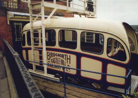
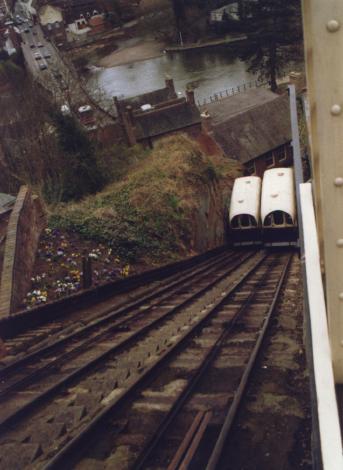
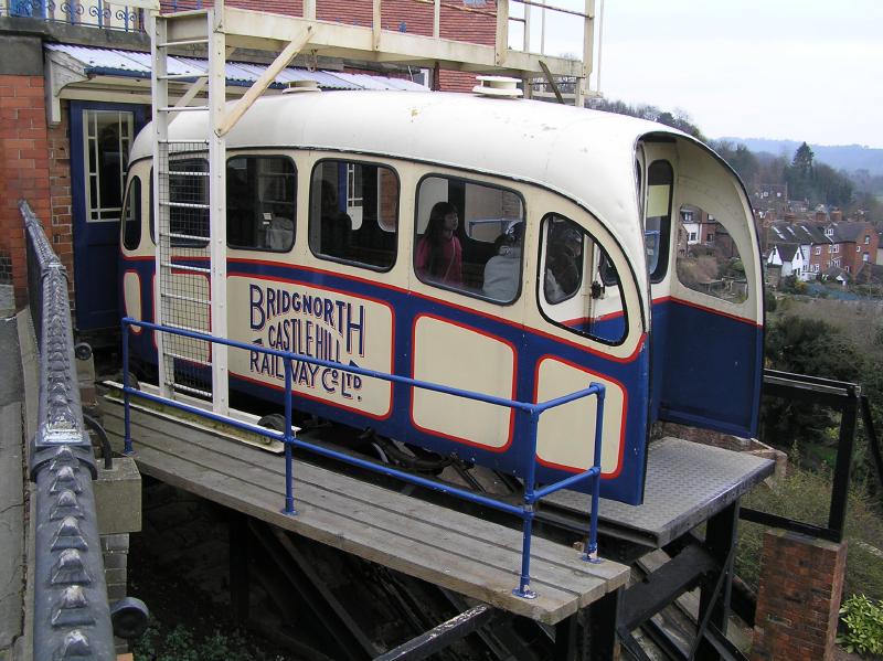
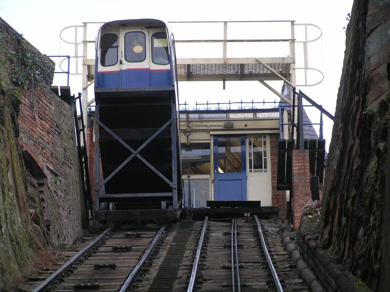
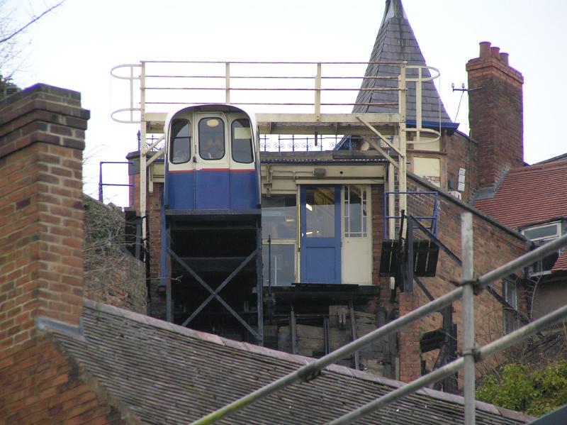
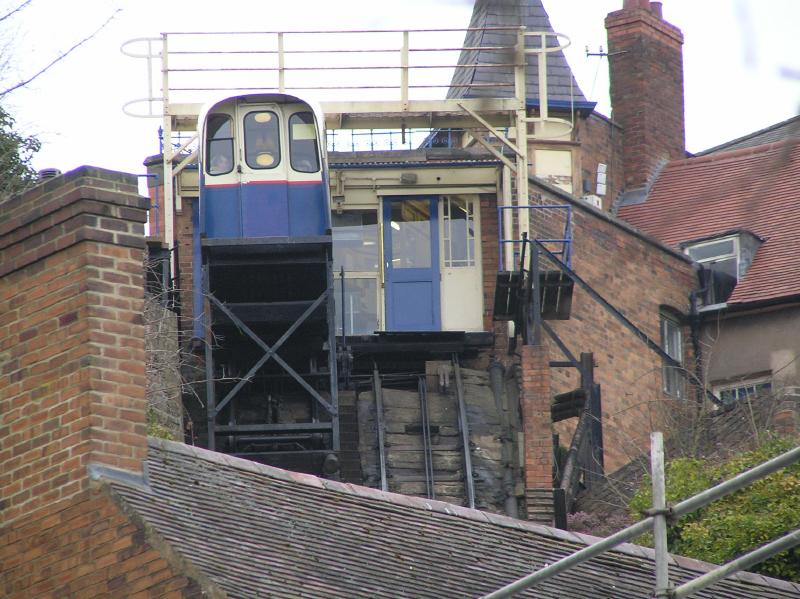
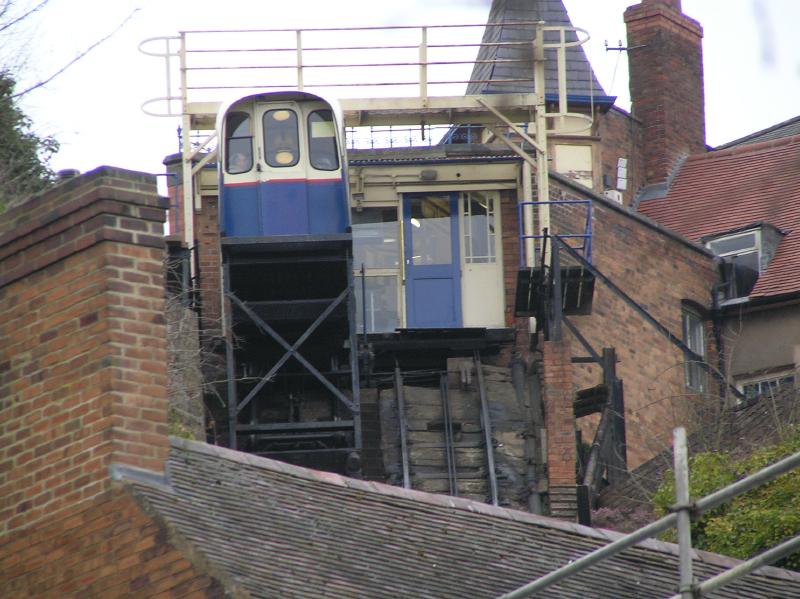
The Castle Hill Railway, Bridgnorth, Shropshire was built in 1892 to connect the high town and low town. It vertically rises 36m over a distance of 61m. The railway operates two carriages on parallel tracks. Connected by steel cables, the carriages serve to counterbalance each other - as one rises to the top station, the other runs to the bottom station. The cars are now powered by an electric winding engine, but were originally driven by a system of water balance, each carriage carrying water ballast in a tank beneath the passenger compartment. It was converted from water / gravity power to electricity in 1943.
Cars
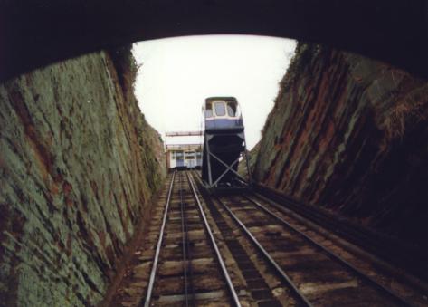
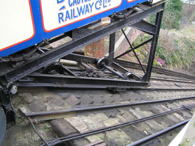
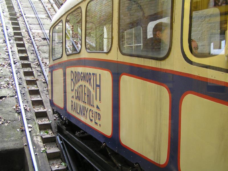
The original cars were of wooden construction, on a steel chassis. The cars were replaced with "up-to-date" cars of aluminum monocoque construction in 1955. Simple sliding doors at each end of the cars run on their original ball bearing rollers. Each car weighs approximately 5.5 tonnes when fully laden with 18 passengers.
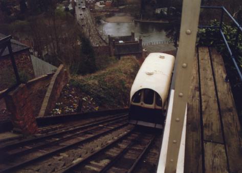
The track
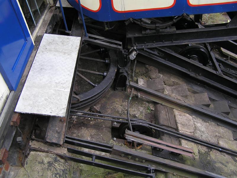
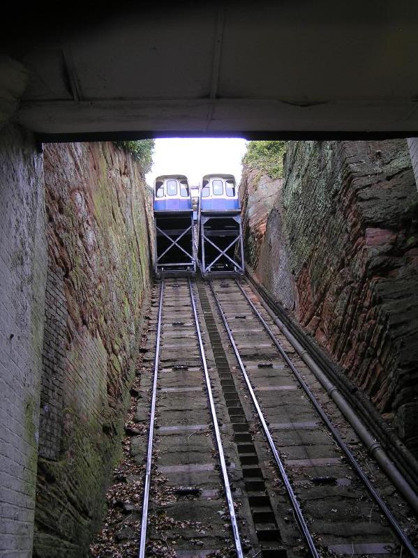
The track is 201 feet long, with a rise of 111 feet and consists of a double run of track - one for each car. Concrete steps run between the two tracks. The tracks are standard bull head rails, of about 1972 vintage. The gauge is 3 ft 6 ins. The original sleepers were timber and were the full width of both tracks. Over the years they have rotted away and were replaced with a multitude of secondary fixings - this allowed the rails moving slightly out of line, and resulted in a less than smooth ride. In order to rectify this problem new steel sleepers surrounded with concrete have been inserted under the existing rails, using standard spring clips as used on main line railways. The Railway remained open during this work, and it took some 18 months to complete. Track rollers supporting the ropes appear to be the original design. The roller is solid steel, supported each end by a ball bearing plumber block. Replacements are being used when necessary, utilising sealed roller bearings.
Winding Gear
The present winding gear is of the type used in collieries. It is situated below the Top Station and was installed in 1955. The ropes wind on to 2 winding drums - one winding on as the other winds off. There is a system of 3 reduction gears reducing the the speed of the motor from 650 rpm down to 30 rpm on the drum. The final gear and winding drums are some 4 ft in diameter.
Compressed Air System
A fail-safe compressed air system operates one of the 4 braking systems. Two large steel weights act to keep brake shoes applied to the two 4 ft diameter brake drums. Compressed air at a pressure of between 50 and 100 p.s.i. operates two vertical pneumatic rams, which act against the weights to remove the brake. As the driver releases the brake, the cylinders lift the weights from the brake drums, allowing the cars to be moved. In the event of a compressed air failure, the brakes would simply be reapplied by the weights.
Electrical System - 110 volts
The low voltage system is used in the Railway's safety systems. These include the four station/carriage doors, the passenger indicators, the two overspeed switches and controllers, the "dead man's pedal" and the drum winding plate switches.
Electrical System - 240 volts
The standard voltage system is used for lighting and power. There is a mains operated radio telephone linking the two stations, in addition to a battery backed system for use in a power failure.
Electrical System - 415 volts
The high voltage operates the 32 hp 3 - phase AC motor through the Drum Controller. This is similar to the system used on trams.
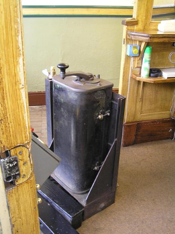
Driving Controls
The driver's two indicator panels consist of 2 air pressure gauges, a speed indicator, a voltage meter, an ammeter, a trip indicator and various speed and door control lights. The controls consist of the motor control handle, which controls the speed and direction of the motor, and the compressed air brake (the brass handle on the right of the picture). In addition, the driver must stand on a floor mounted "dead man's pedal" in order to disengage the brake.
Ropes
There are three steel cables or ropes - a separate one from each car to the winding drum, and a balance rope running from one car to the other via the winding wheel. These are 26mm multi-strand ropes tested to an actual breaking strain of 42 tonnes. They are examined in great detail for defects every 4 months, and are replaced as a matter of course every 3 years.
www.bridgnorthcliffrailway.co.uk/
 <
<


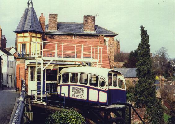
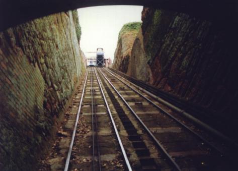
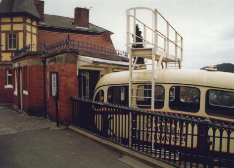
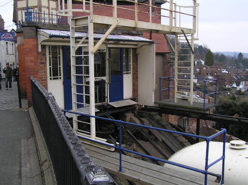
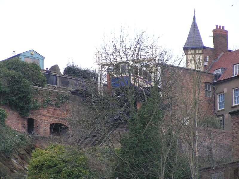
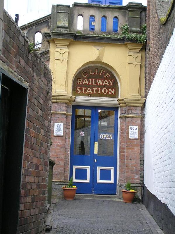
The actual start of the construction work began on 2nd November 1891. Initial work was much hindered by the discovery of caves set into the cliff-face - one cave was so large it was necessary to support the roof to avoid slippage and subsidence. Another problem facing the construction work were the many houses built into the cliff face around the site - in some cases, the effect of excavating the cutting was to remove supporting walls from the poorly constructed dwellings. At either end of the track station buildings were constructed.
The original patented design of the railway was for a single track with two cars, with a crossing point mid way between top and bottom, but this was abandoned in favour of a double track. When finished, the track measured 201 ft long, with a vertical rise of 111ft. This gave the railway an incline of 33°, the steepest in England.
The rails were secured to sleepers which were themselves bolted into solid rock. At the upper end of the track, the hauling pulley was built on solid concrete foundations, the supporting buttresses of which carried a considerable distance down the track. Flat bottomed rails were used and the entire line was ballasted with concrete to avoid any slippage. Horizontal rollers were set into the track at regular intervals to support the cables.
Each car was mounted on a triangular frame of steel girders which housed a 2000 gallon water tank. The method of power was simple - the tank on the car at the top was filled with water from a 30,000 gallon tank mounted on the roof of the top station. When the tank was full, the total weight of the car was more than 9 tons, easily enough to counterbalance the bottom car with its 18 passengers. As the top car was being filled, the tank on the bottom car was being emptied, and the water pumped directly up to the top station tank by means of a pair of pumps driven by independent Forward Gas Engines.
The cars were linked by a pair of steel cables, the breaking strain of which was calculated to be 15 times the normal working load of the cars. In addition, the cars were fitted with rapid gripper brakes which automatically engaged should the rate of descent become too great. A second manually operated brake was the responsibility of the brakeman who rode on the bottom platform of each car.
The railway opened on July 7th 1892. The ceremony was performed by the Mayor, and in celebration the local townspeople enjoyed a public holiday. Between July and September 1892 over 50,000 passengers used the railway. The railway ran continuously for the next 41 years, until April 1933. In May 1934 it was reopened by new shareholders.
2006 Pics


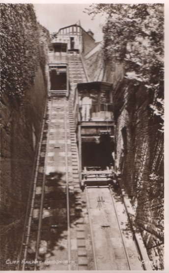
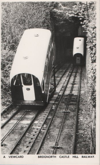
Old Postcards
| Date Opened | 7/7/1892 | Length | 201 ft |
| Gradient | 1:1.8 | Track Gauge | 1118 mm |
| Number of Cars | 2 | Open to Public | Yes |
| Funicular Type |  | Track layout |  |
| Power Source |  | Railway Status |  |